
Operational Tests Phase II
Objective
The pilot project is intended to provide the technical basis so that migration of a DAC can be implemented Europe-wide. In the process, the aim of phase II was the implementation of coupling and driving trials in scenarios which equate to regular operation of rail freight transport (RFT). For this purpose, more than 25 shunting yards were used to test the functions of the DACs. This included trials on the (automated or manual) hump, in the gravity yard, in the shunting yard with retarder mode and in the port terminal with railway sidings or customer railways sidings. Furthermore, the operational processes were assessed and optimisation opportunities which would be favourable to the introduction of the DACs into regular operation, were discussed. In the same way, the operation of the DACs was assessed and requirements for optimisation for this purpose were identified.
The investigations focussed on both the mechanical behaviour of the coupling designs and the electrical characteristics of the electric couplings for power and data transmission.
Test cases
The DAC tests are carried out in actual operating scenarios. The following key test areas and corresponding test scenarios were defined:
MEASURING CONCEPT
Mechanical measurements
The following variables are measured at the wagons of the individual wagon groups:
Current and data measurements
An overview of the current and data measurements in phase II is shown below.
MEASURING TECHNOLOGY
In phase I, the focus was on detailed measurements of the constantly identical wagon configuration and the comparison of the various DAC designs. Electricity for charging the systems or for operating the hardware was generally available.
With the beginning of phase II, the trials were no longer carried out on a specific test site but rather at facilities all over Europe. The journeys to these destinations were also used systematically in order to gain knowledge of the performance of the train during the journey. For this purpose, the measuring system was designed with two modes. For train journeys, all the wagons were either connected via the DACs or by cable. The electricity supplied via the DACs was thus used to operate the measuring technology. All the measured data was transmitted directly to the measuring wagon in this case. In this mode, it was not possible to disconnect the coupling points readily because of the cables.
As a result, these connections were not in place for trials in shunting operation and the wagons had to be capable of carrying out measurements independently. For this purpose, the individual wagons were equipped with their own batteries and their own data capture devices.
There were a total of six different equipment categories which are listed in the following table.
Indication of the categories for wagons equipped with wagons, including installed sensors
| Category | Capable of carrying out measurements independently | Sensors | Carriage types |
|---|---|---|---|
| A |
|
· Strain gauges, coupling forces · Brake line pressure · Coupling deflection · Coupling head acceleration, E-coupling, wagon body · Speed · GPS |
S wagon H wagon |
| B |
|
· Brake line pressure · Coupling deflection · Carriage body acceleration · Speed · GPS |
H wagon |
| C | X | · Brake line pressure · Electr. measuring points |
Z wagon E wagon |
| D |
X |
· Coupling deflection · Carriage body acceleration |
Z wagon |
| E | X | (Carriage is used as a signal amplifier only) | S wagon |
| F | X | – | Uas wagon F Wagon |
Test locations
The tests are performed at operating locations and on routes with specific characteristics.
The marshalling yards and an example network of the routes to be travelled during field testing until March 2022 are shown in Figure 1. Location which are shown in light grey are optional and will be approached if the time and route map allows.
| Location | |
|---|---|
| Test sites DE | |
| Mannheim/Ludwigshafen | |
| München Nord | |
| Ingolstadt | |
| Nürnberg | |
| Kassel/Bebra | |
| Bremerhaven | |
| Bremen Sebaldsbrück | |
| Test sites Switzerland | |
| Basel | |
| Zürich | |
| Gotthard | |
| Test sites Austria | |
| Rankweil | |
| Selzthal | |
| Niklasdorf | |
| Wien | |
| Test sites Poland | |
| Poznań Franowo | |
| Wapienno | |
| Dąbrowa Górnicza | |
| Zabrzeg Czarnolesie | |
| Zebrzydowice | |
| Test sites Czech Republic | |
| Ostrava | |
| Brno-Maloměřice | |
| Plzeň | |
| Test sites France | |
| Straßburg | |
| Test sites Luxembourg | |
| Bettemburg | |

Demonstration Train
in Phase II
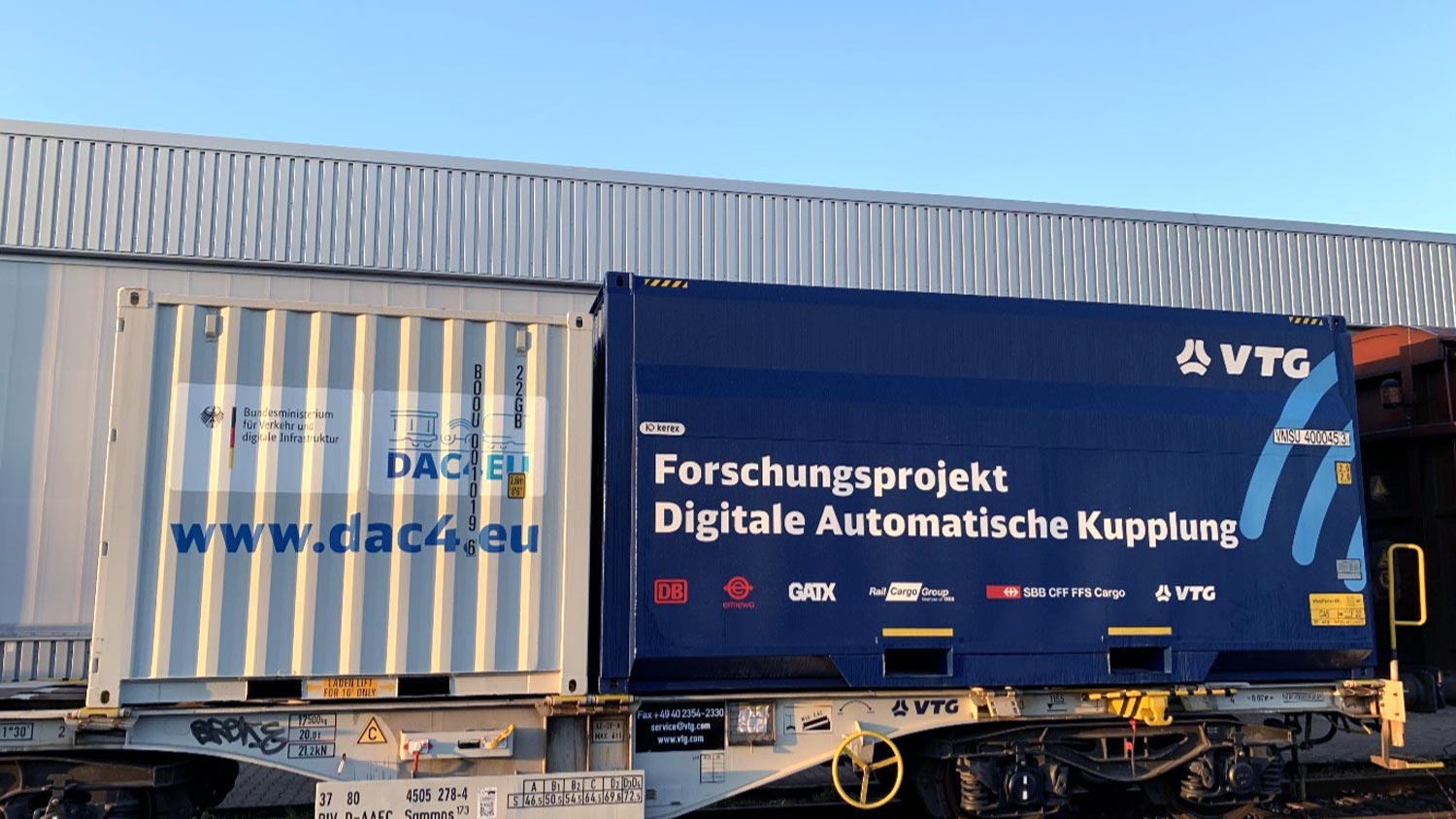
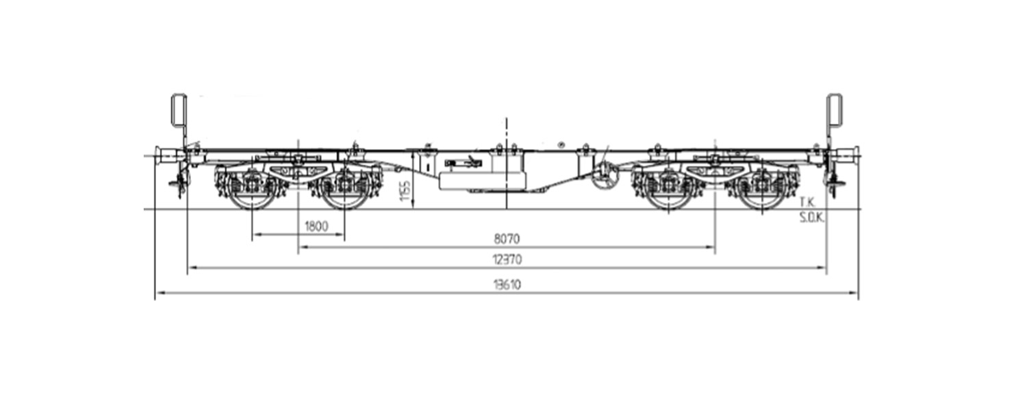
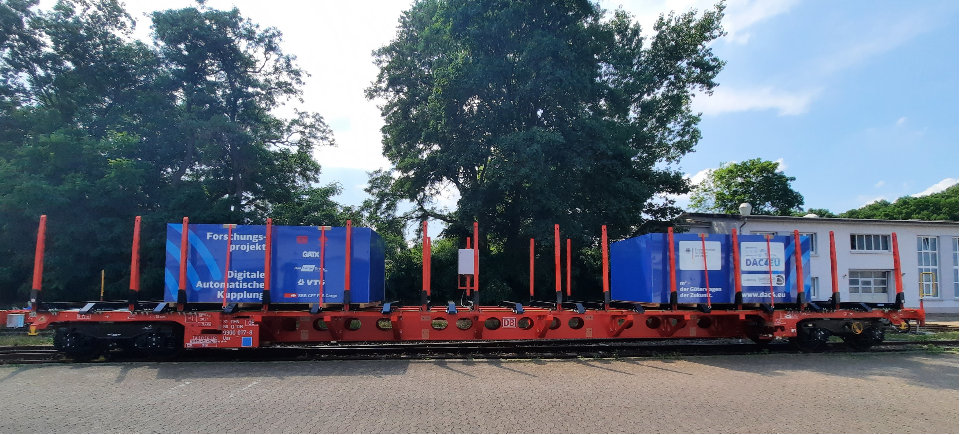
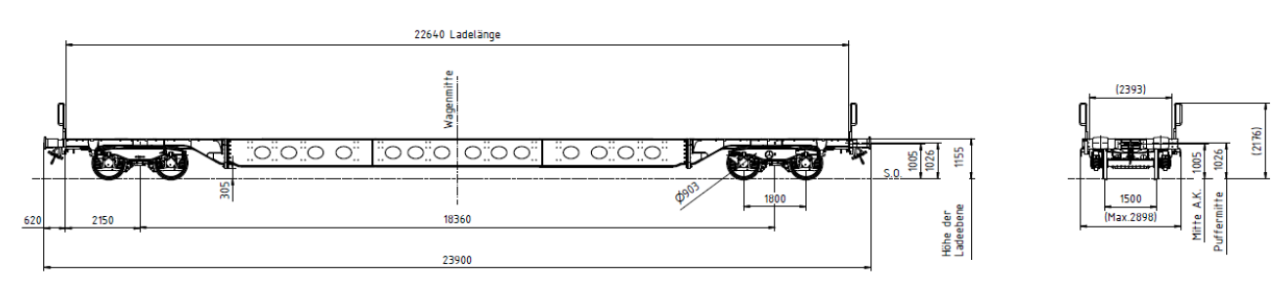
For phase II, the DAC4EU demonstrator train was gradually extended to 20 wagons with the selected Scharfenberg or latch-type coupling design. In the process, three new wagon types were added:
Within the scope of the trials, the train integrity check was used to monitor the communication systems. At all times, it was known that the train was complete, meaning that this information had to be supplied to the systems without interruption.
The following image shows the final confiiguration of the demonstrator.
Final train configuration:

# Voith
# Dellner
⬤ UIC screw coupling
⬤ DAK with electric motor
⬤ DAK with lever action
⬤ DAK with horizontal lever
◆ C-Pressure/HLL-Pressure Sensor
◆ Ep-light System
xxx-x Wagon number

automation components
in the demonstrator train
A further focus of the work during phase II is the selection of suitable automation components in order to verify the functionality of the power and data supply in the demonstrator train.
The following functions or automation components are to be set up in phase II:
Train initialisation
When the train is initialised, the freight wagons within a block train connect to the communication network. The first step when preparing an intelligent freight train is to initialise the train, as the train preparation processes can only be automated if it is also known which freight wagons are in the block train. The train initialisation is created as a function of the communication system and should already be available in phase IIa.
Recording the
wagon sequence
and orientation
The wagon sequence and, in the case of defined trains (e.g. with automobile traffic), wagon orientation (front/rear) is also recorded by a member of operational staff before each train departure. This is done by comparing with the list of wagons which is available to the loc driver and is generated from the IT system of the power company with the actual sequence in the block train. The wagon sequence and orientation is prepared as a function of the communication system and should also already be available in phase IIa.
Train integrity test
At present, an end-of-train signal must be connected manually to the last wagon of the train before every train departure. This aim is to ensure that if the train is separated when in motion this is detected, even if the check of the block section by axle counter or track power circuits is omitted or disrupted. If this is not the case, the train is stopped and the section blocked as the train may have become separated. Furthermore, detection of the train integrity is also one of the main prerequisites for introduction of ETCS Level III in the case of freight trains.
For the first time in rail freight transportation, a train integrity check is to be set up as a function of the communication system in the demonstrator train. This means that the wagons in a block train do not only connect to the communication network before the train departs; they also do so at regular intervals during the journey. This lets the driver of the traction unit know if the block train no longer contains all of the connected freight wagons. A basic rule that applies for all automation functions is that they are only displayed in demonstration mode without taking safety requirements into consideration. However, it is explicitly pointed out in the case of the train integrity check that this is purely a demonstration of the function. As the safety requirements for a train integrity check are very high, this kind of system, which has been developed to meet the safety requirements, should be specified in a separate research and development project.
Electro-pneumatic brake
The freight wagons of the demonstrator train are to be equipped with an EP brake “light”, along the same lines as the research project “Construction and Testing of Innovative Freight Wagons” commissioned by the BMVI. This requires the installation of so-called EP brake valves and control of these valves via an additional 110 V power line (which is in fact already envisaged in the design of the electrical energy system and the electrical coupling contacts of the DAC). All freight wagons in the block train can brake simultaneously with the EP brake. This leads to shorter stopping distances and especially also to smaller longitudinal dynamic tractive forces. Due to the longer lead times of EP brake valves, this function can only be installed in phase IIb.
Automatic brake test
At present, a manual brake test must be carried out before each train departure. This involves walking up and down the train several times and checking the application and release of the brake. Several companies in the rail industry are currently working on prototypes for an automatic brake test. In phase IIb it is envisaged that an automatic brake testing system by one manufacturer is fitted to three freight wagons respectively. 12 freight wagons in total are to be equipped with this system. This is not sufficient to carry out a full automatic brake test for the demonstrator train with 24 freight wagons. However, as the prototype systems are not compatible with one another, an automatic brake test for the complete train cannot be carried out in any case. However, the purpose of installing the prototypes is to demonstrate the technology and an automatic brake test can be carried out on each freight wagon to which the same brake testing system is fitted. Additionally, electricity is to be supplied to the brake testing devices via the 110 V power line or the buffer battery in the freight wagon.
Telematics and sensor technology
Telematics systems and sensors by various manufacturers will be fitted to the freight wagons of the demonstrator train. The basic telematics unit is already used in rail freight traffic to perform familiar standard functions, such as position definition or recording of mileage. Furthermore, sensors with different functions, such as impact detection, recording the loading state, temperature and pressure detection and, if applicable, sensor technology for monitoring doors, will however be tested in the demonstrator train from phase IIa onwards.
The automation components which may be used in the demonstrator train do not yet represent a final selection or basis for a standardisation. Safety requirements (Safety Integrity Level – SIL) are not yet analysed in the applications. The purpose of the selected automation components is therefore only to demonstrate the function and show how the DAC can automate the rail operation processes by providing a continuous electrical power and data line. All stakeholders should then be able to see the shifts in productivity that can be achieved in rail freight transportation using automation components in “intelligent freight trains”.
FIELD TESTING AND SCHEDULE
The start of field testing in phase IIa was in July 2021 at the shunting yard in Mannheim.
Following journeys and operational tests in Germany, tests were carried out for four weeks in Austria and Switzerland respectively with the demonstrator train in shunting yards, on journeys and on railway sidings from the start of February 2022. In Austria, it was possible to carry out trials in winter conditions. It was thus possible to confirm the knowledge gained from the climatic chamber trials in regular operation too.
In Switzerland, the demonstrator train was tested on mountainous routes, including the Gotthard Panorama route and in the Gotthard Base tunnel. Shunting trials were also carried out on Europe’s most state-of-the-art facilities, at the Basel RB2 shunting yard. In this case, shunting is performed completely without a locomotive. The facility is sufficiently automated so that external intervention is not necessary.
Based on these trials, in the second step of phase II (b), it was then possible to integrate further countries into the testing. This, in July and August 2022, testing was carried out in Poland and in the Czech Republic. In the process, trips were made to special locations in Poland, e.g. a facility with a rotational tilter, which are often in use in eastern Europe, or a coking plant in which there is a particularly dusty environment. In each case, the functionality of the mechanical, pneumatic and electrical connections was tested. In the Czech Republic, trials were also carried out at shunting yards and the journeys were used for testing the communication systems installed on the demonstrator train.
In September 2022, the demonstrator train was be presented at Innotrans 2022 in Berlin.
In the autumn of 2022, trials were carried out at the shunting yard in Sebaldsbrück near Bremen, and the DAC4EU demonstrator also made a visit to a seaport terminal in Bremerhaven.
After the shunting trials, a further 18 bulk goods wagons, fully loaded with gravel, were added to the DAC wagons in order to form a goods train which was as long and as heavy as possible. In this composition, the demonstrator travelled more than 1,300 kilometres. In the process, not only the measurements of the electrical connections and the connections to the communication systems were recorded, but also the resilience (tensile/compressive forces) of the mechanical connections was tested.
RESULTS
The generally good suitability of the DAC prototypes for use in shunting operation had already been demonstrated during the detailed trials in phase I. The systems largely met the demands made with aplomb. Minor difficulties were addressed by directly involving the manufacturers.
For field testing in phase II, the focus of the assessment was expanded. Instead of assessing the couplings largely in isolation, the “DAC system” was now assessed as a whole. This refers to the integration of prototypes into different wagons and thus also into different operational processes, and their interaction with a wide range of infrastructures. This results in a complexity which makes for other challenges than those in phase I.
When operated on level ground, the benefits of the DAC were clearly demonstrated with the current prototypes. Coupling and decoupling is performed more quickly, is physically less demanding and, at least for coupling, can be performed fully automatically without the need for operational actions on the coupling. The feedback from operating staff and also a few external customers is consistently very positive. The benefits, such as operation in tight track bends without pretreatment (tested down to a bend radius of 45m), also show the potential process simplifications which are possible with the systems.
If the potential of the electrical connection (electrical and data) is included in the assessment, it can quickly be demonstrated which processes can be facilitated in future and which efficiency improvements are possible in the process.
A further essential part of rail freight transport is main line operation. In this regard, it has been demonstrated that systems handle both light-weight and heavy trains with aplomb. However, some details are still open in this area, and will need to be assessed thoroughly over the course of the project. This includes, for example, the longitudinal dynamic behaviour of the train. The aim is also to test the DACs to their limits. In this particular case, in the absence of a traction unit with DAC, it was only possible to test the limits of the screw-type coupling on the traction unit.
The situation is different, above all when it comes to hump shunting, but also in part when it comes to push shunting. There are still challenges in this area which need to be overcome. Some of the available solutions and those which have also in part been tested, need to be combined to form a single product and some still need to be developed further.
One aspect which has not yet been assessed sufficiently within the scope of the testing performed henceforth, is the permanent operational stability of the systems. Repeated damage has occurred but it did not restrict the basic functions or, above all, the safety-related functions. However, it is imperative to assess the subsequent service life of the systems, at least in the form of a simulation on test benches, for example.
In relation to the electricity and data part of the testing, one can declare that a connection can be established reliably. The E couplings will be developed further by the manufacturers at the end of phase II meaning that the knowledge gained can only be transferred to apply to the mechanical robustness to a limited extent. It has been shown, above all when it comes to the transmission of data, that the interaction of the mechanical components, contacts and the communication system implemented so far still needs to be improved with regard to robustness.
For a detailed report of the trials from phase II on the BMDV (Federal Ministry of Transport and Digital Infrastructure) website, visit the following link: https://bmdv.bund.de/SharedDocs/DE/Artikel/E/dak-demonstrator-phase-2.html
Thanks to the extension of the research project by the BMDV (Federal Ministry of Transport and Digital Infrastructure), DAC4EU can continue to provide a testing platform which is unique in Europe, in order to work on the solutions for the existing challenges.

