
Detailed Tests Phase I (Dennis CURRENT EDIT)
In phase I, four DAC prototypes were subjected to intensive individual comparison trials. The aim was to gather sufficient knowledge and then submit the results to the European DAC Delivery Programme (EDDP) in order for this European committee which is made up of 84 partners, to be able to make a selection decision for a coupling system. The results were discussed and assessed in detail, with the EDDP being able to announce its decision to select the Scharfenberg latch-type design on 21 September 2021. It was then selected for introduction Europe-wide.
In this section, we take you through phase I and describe the testing concept and procedure, and summarise the results. You can download the detailed test reports from the BMV website.


Technical measuring equipment
For the tests in phase I, measuring technology was deployed on the freight wagons, which can be divided into three groups:
- Measuring technology necessary for mechanical and pneumatic testing
- Measuring technology that proves the functionality of the energy supply
- Measuring technology for proving reliable data communication
These three groups are described in more detail below.
Mechanical and pneumatic measuring technology
The physical measured variables that were recorded during the tests and the sensor types used for each are listed below.
Measured variables | Sensor | Components | Vehicle | Exact position |
|---|---|---|---|---|
Coupling force | Strain gauge (SG) | Push/pull rod | Hbbins 306 | Both couplings |
| Acceleration coupling(Mechanical part) | Accelerometer(3-axis) | Coupling head | Hbbins 306 | Both couplings |
| Acceleration coupling(Electrical part) | Accelerometer(3-axis) | E-coupling | Hbbins 306 | Both couplings |
Wagon speed | Incremental encoder | Wagon | On rolling wagon per coupling test | Underneath the vehicle |
Driving distance of the wagon | Radar sensor | Wagon | On rolling wagon per coupling test | Underneath the vehicle |
Main air line pressure | Pressure sensor | Wagon | Using a coupling point as an example | On the control valve |
Brake cylinder pressure | Pressure sensor | Wagon | Using a coupling point as an example | On the control valve |
Position of the driver’s brake valve | Draw-wire encoder | Driver’s cab | Traction unit | Control lever for the driver’s brake valve |
Components for testingthe power supply and data communication
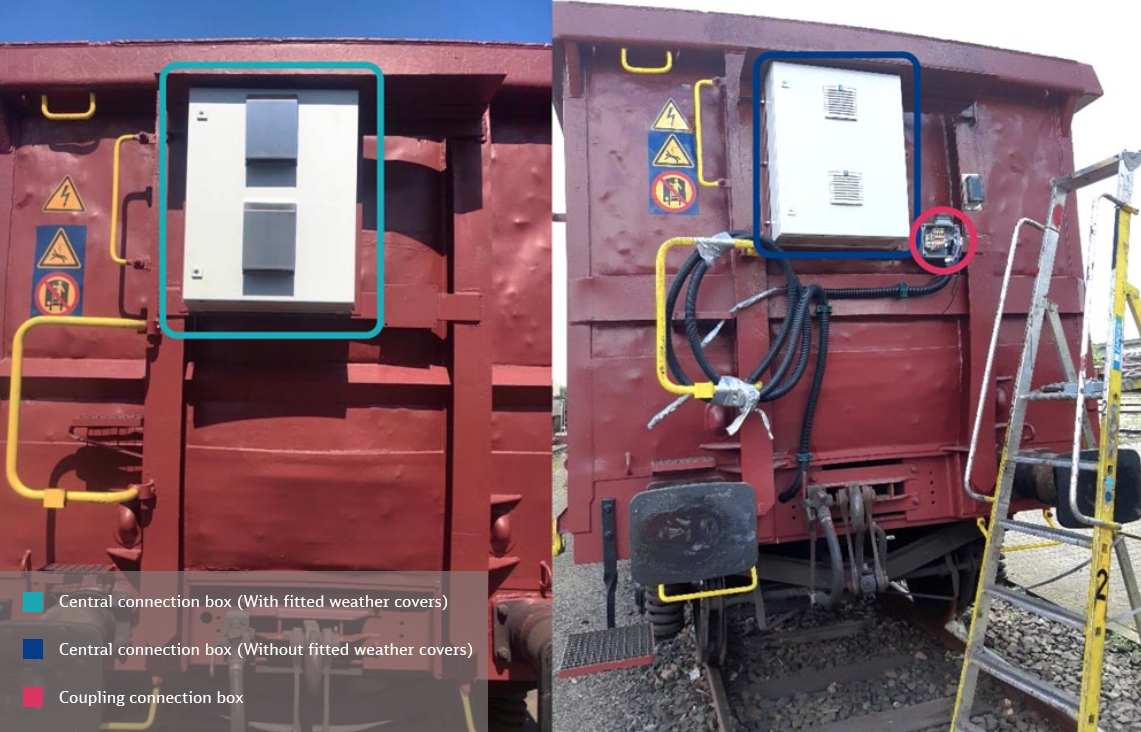
The components for testing the power supply and data communication are listed in the table below. These are integrated into the central connection box.
Module | Description |
|---|---|
| Industrial PC | The embedded PC is the central element for controlling the communication systems. Integrating all systems is achieved through communication system-dependent software modules. The embedded PC contains software for testing and analysing the communication links. This component also controls the tests. |
| CAN communication module | The (2-port) CAN FD communication module converts the CAN data packets to Ethernet. |
| Powerline module | For testing the Powerline system |
| WiFi access point/ client | For testing the radio system as a communication link between the wagons, a WiFi access point is used, which can also be set to client mode. |
| Relay | An industrial relay is used to bridge the CAN connection. This allows the CAN bus to be operated in segmented communication system mode as well as in continuous line mode. |
| Ethernet switch | The Ethernet switch bundles the various communication systems for connection to the Ethernet port of the industrial PC. If necessary, an adapter for modules from parallel projects can also be connected here. |
I/O module | I/O modules are used for the following functions:
|
| Other | Installation material for setting up the wagon box |
| Power management battery | Battery head station: The module automatically charges the battery when powered by the 110V DC line. If the power supply fails, the battery is automatically switched on to provide power. If necessary, you can query the battery’s state of charge (feed-in/discharge power). |
Battery | Battery for connection to the power management |
| Power supply unit (110V DC to 24V DC) | Conversion of the voltage on the 110V DC supply of the train bus to the internal wagon voltage level of 24V DC |
| Signal lamp | Display visible outside the wagon box to show conditions of the wagon (voltage present on 110V DC line, coupling condition if information is available) |
Test concept and tests
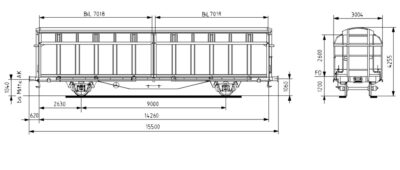
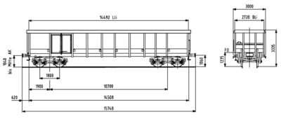
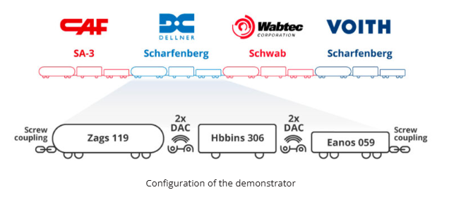
In phase I, the procured couplings were each tested using a detailed test concept agreed with the EDDP. The wagon configuration described at the beginning and the technical measuring equipment were applied.
Phase I was started in September 2020 after the demonstrator was installed (June to September 2020). However, due to unresolved technical questions regarding the coupling prototypes, the test programme could not be finalised by February 2021 as planned. Phase I was therefore extended until 30/06/2021 in close cooperation with all coupling manufacturers.
Coupling and driving tests
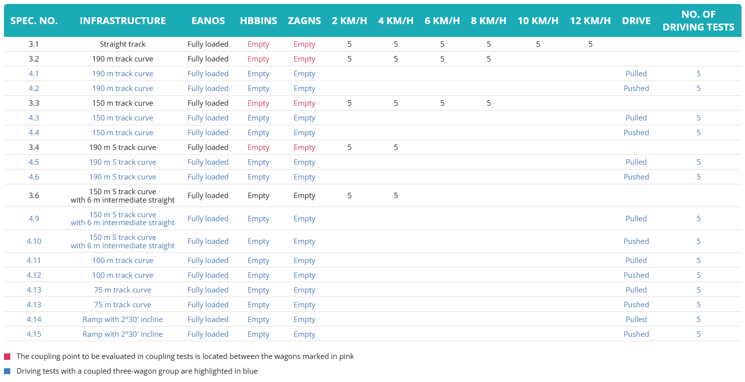
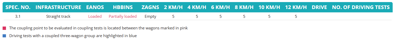
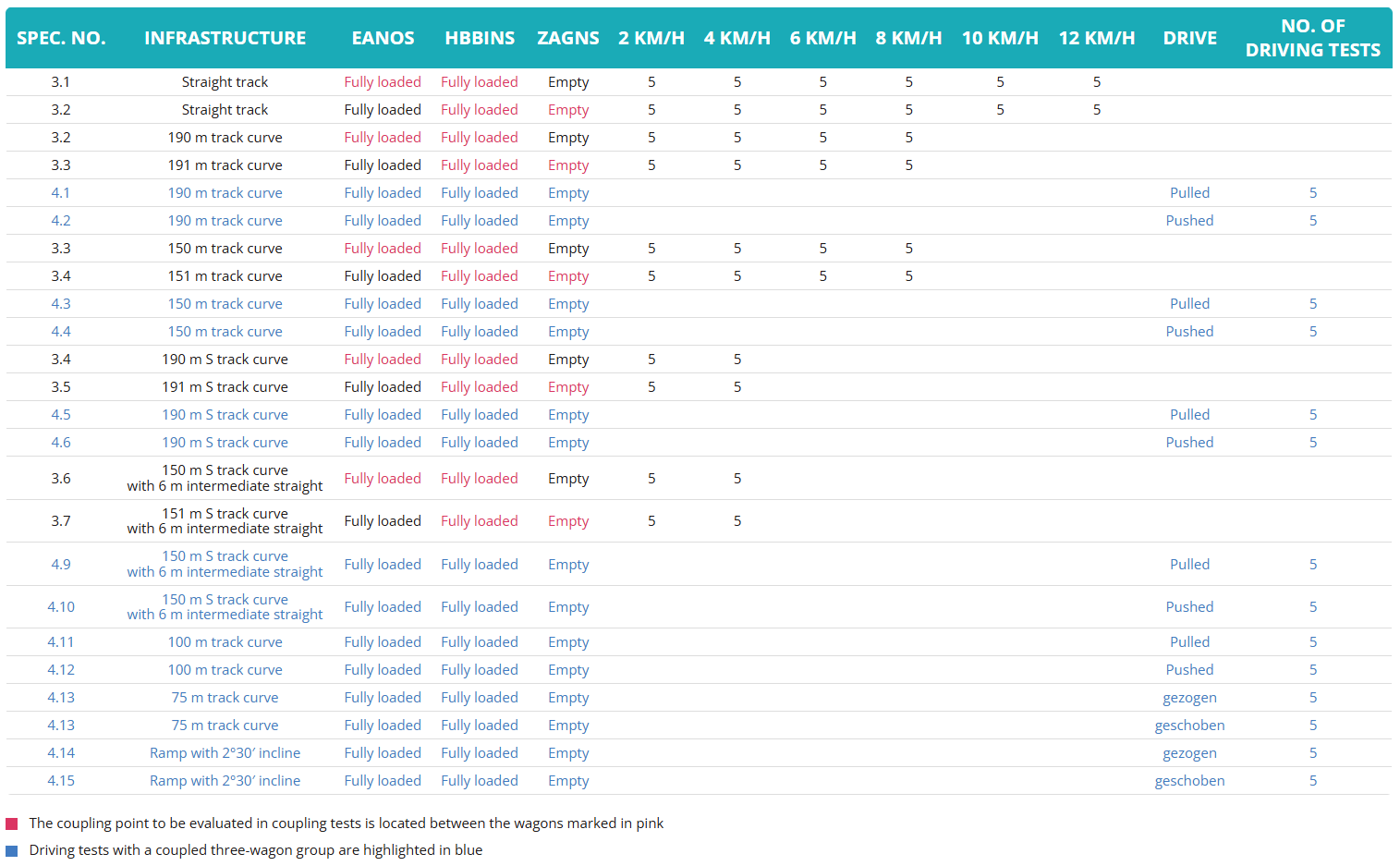
The mechanical tests included coupling tests and operational tests (passing through different track geometries). Carrying out a large number of tests at different speeds in different geometries were necessary to prove a reliable coupling capability and unrestricted operation. To better assess the significance of a result and its repeatability, the tests were repeated five times.
Loading conditions 1
ResultsThe results of the coupling and driving trials with the tested prototypes are very different. One thing the couplings of all manufacturers have in common is that deficiencies and weaknesses were identified over the course of the tests, and repairs were required on all coupling designs. It was only possible to generate a comprehensive data base for all the prototypes included in the test by extending the test, as explained in the introduction, and with the repairs carried out by the manufacturers. The following examines the three DAC designs individually and lists the results in summary form for each design.
Scharfenberg design from manufacturer VoithThe driving trials ran overall without any noticeable problems. All infrastructures could be negotiated without restrictions. The coupling procedures with the first version of the Voith DAC failed in numerous cases. The electrical coupling procedures were also assessed as “not successful” in many cases (e.g. 24 of 72 trials at 6 km/h not successful). The contacts often externally showed clear wear marks after just a few trials which was determined as the cause for the negative assessment. In detail, it proved to be only a few contacts which had failed permanently. Voith has developed and made available a version 1.2 on which the coupling head has been adapted. During the coupling trials with this second version of the DAC design, the coupling procedures were successful at lower and medium speeds. The carriages only recoiled with not coupling procedure during coupling trials at 12 km/h. The problems with the contacts in the electrical coupling remained unchanged with version 1.2 of the prototypes.
Latch-type design from the manufacturer DellnerThe first generation of the Dellner latch-type design did not meet the requirements for mechanical strength, meaning that Dellner had to pronounce restrictions in relation to the coupling impacts. Specifically, coupling impacts at speeds higher than 10km/h were not permitted. However, the mechanical and pneumatic connections during the coupling procedures tested 100% successfully allowing for the restrictions. The second generation of the coupling included a mechanical upgrade of the DAC and the implementation of a stabilisation joint to improve the resistance to derailing.
The electrical coupling procedures were assessed as “not successful” in many cases (e.g. 27 of 27 trials at 2 km/h not successful). Also, the contacts often externally showed clear wear marks and the moving contact side jammed after just a few trials. In many cases, as is the case of the Voith coupling results, the failure of individual contacts was the cause for the negative result of the assessment. However, in at least one case, both E-couplings failed completely.
The driving trials with the generation 1 prototypes ran overall without any noticeable problems. All infrastructures could be negotiated without restrictions.
Schwab design from the manufacturer WabtecThe Schwab prototype also required a second version in order to produce results which were suitable for assessment. With the DAC prototypes tested, the mechanical connection during the coupling procedures tested 100% successfully. The pneumatic coupling did not work in some cases (e.g. 12 of 104 trials at 2 km/h not successful). It was in part possible to couple Zags and Hbbins carriages in the 100 metre bend depending on the load of the Hbbins. It was not possible to couple Zags and Hbbins carriages in the 75 metre bend.Constructional weaknesses on the moving parts of the electrical contact coupling arose during the tests. As a result, during most of the trials, the reports state that the electrical connection was not successfully closed (e.g. 48 of 104 trials at 2 km/h not successful).Selected follow-up tests were carried our with the retrofitted E-couplings. In the process, it was only possible to reassess a limited speed range. In these follow-up tests, the measures taken were successful. There were not noticeable significant wear marks in the case of the E-contacts.
The driving trials were mechanically and electrically 100% successful. However, problems with the pneumatic connection were identified (pneumatically coupled in 30 of 142 trials not successful). In this case, there were no short-term air losses.
Over the course of the trials, the required force in order to separate two decoupled carriages proved to be greater and greater. This behaviour was eradicated towards the end of phase I by Wabtec by directing the coupling heads sideways in advance using an adapter on the coupling rod. As a result, the decoupling force seemed to have returned to within an acceptable scope. It was only possible to test this to a limited extent within the remaining time.


Results
In the banking trials, none of the couplings fell short of the required minimum value for the sustainable longitudinal compressive force of 200 kN for a screw-type coupling. Two of the three DAC prototypes tested were even able to clearly exceed the reference level of the screw-type coupling (in part by more than a factor of 2).
The Scharfenberg and latch-type designs derailed at 500 kN and 400 kN respectively. The trials with the Schwab design were stopped at 400 kN as there had already been a clear wheel reaction and, on request from the manufacturer, derailing was to be avoided. In addition, none of the couplings reached or exceeded the limit values for wheel lift and the highest permissible transverse wheelset bearing force. However, derailings occurred during the trials. It was not possible to conclusively clarify the reason for this circumstance, and it could be the focus of further research. The data base resulting from the trials could be essential for the path towards European approval.
Electrical tests
Each of the four DAC prototypes is equipped with an electrical coupling (E-coupling). In the case of the Schwab and the SA3 design, the E-couplings were each fitted underneath the mechanical coupling. On the Scharfenberg and latch-type designs, it was fitted above. Both the SA3 and the Scharfenberg and latch-type DACs have spring/fixed contacts. On the Schwab DAC, pin/socket contacts are installed.
Overall, four measurements were performed:
- Measurement of the contact resistance
- Measurement of insulation resistance
- Power transmission via the train
- Charging and discharging behaviour of the batteries
In the process, the measurements of the contact resistance and the insulation resistance measurements were carried out before starting the mechanical coupling trials as well as during and after the trial programme. In the case of (1), the DAC prototypes in coupled state whereas in the case of (2), they were in a decoupled state. The power transmission (3) was measured for each coupling design in the 3-carriage set and in a coupled state. The charging and discharging behaviour of the batteries (4) on the other hand was tested in the complete train set with nine carriages.
ResultsThe acceptance criteria during the measurements of the contact resistances were only met in part by the Scharfenberg, latch-type and Schwab DAC prototypes as the maximum resistances were partially only achieved for the supply and data lines (in the case of the latch-type design) or only for data lines (in the case of the Scharfenberg and the Schwab design).
The insulation resistances of the Scharfenberg design were too low. The acceptance criteria for (3) and (4) on the other hand were met by all E-coupling designs.
The following table summarises the results of the measurements:
| E-coupling | E11 Contact resistances (1) | E12 Insulation resistances (2) | E15 Power transmission (3) | E16 Charging/Discharging behaviour of the batteries (4) |
|---|---|---|---|---|
CAF | not met | met; (ohne Abschlussmessung) | not tested | not tested |
Dellner | partially met | met | met | met |
Voith | partially met | not met | met | met |
Wabtec | partially met | met except for 1 contact point; only partial final measurement | met | met |
Trials for power and data communication
An essential component of a DAC is the connection for power and data between the carriages. Therefore, three different communication systems were tested within the project:
- a system which uses the power lines: Powerline PLUS,
- a radio technology between the carriages: Wireless LAN and
- a 2-wire solution using separate lines: CAN-FD
The aim of the trials for power and data communication in phase I was to select a suitable communication topology for the field testing in phase II. The tests showed that all three communication systems are suitable for further evaluation in phase II. The trials in phase II have since provided further decisive results for the selection of a communication system for normal operation. The flow of data and power was tested in both the individual carriage groups and in the entire train set with 12 carriages. In the process, the connection to the carriage group was bridged with the SA3 design. When it came to the measurements in the individual carriage groups, no dependency on the coupling design was determined. In the train set, the communication systems were tested for resilience and resistance to interference, and stable communication was demonstrated.
An overview of data communication experiments:
No. | Communication system | Type | Single wagon/Train |
|---|---|---|---|
D11 | Powerline (before coupling tests) | Channel measurement | Single wagon |
D12 | Powerline (before coupling tests) | Channel measurement | Train |
D13 | CAN-FD | Channel measurement | Single wagon |
D14 | CAN-FD | Channel measurement | Train |
D15 | Powerline (after coupling tests) | Channel measurement | Single wagon |
D16 | Funk | Channel measurement | Single wagon |
D17 | CAN-FD (after coupling tests) | Channel measurement | Single wagon |
D18 | Powerline | Data communication | Single wagon |
D19 | Powerline | Data communication | Train |
D20 | CAN-FD | Data communication | Single wagon |
D21 | CAN-FD | Data communication | Train |
D22 | Radio | Data communication | Single wagon |
D23 | Radio | Data communication | Train |
Test conditions
The conditions and temperatures under which the coupling and uncoupling behaviour is tested:
Temperature | Ambient conditions | Speed | Number of repetitions |
|---|---|---|---|
45°C | Dry | 2-5 km/h | 5 |
45°C | 90% humidity | 2-5 km/h | 5 |
0°C | Wet (slush) | 2-5 km/h | 5 |
-5°C | Wet (slush) | 2-5 km/h | 5 |
-10°C | Dry | 2-5 km/h | 5 |
-10°C | 3-5 mm of ice on coupling face, coupling (coupled) | 2-5 km/h | 5 |
-25°C | Dry | 2-5 km/h | 5 |
-25°C | 3-5 mm of ice on coupling face, coupling (coupled) | 2-5 km/h | 5 |
Ergebnisse
Die Ergebnisse der Klimakammerversuche zeigten auf, dass alle drei DAK-Prototypen Probleme beim Kuppeln der E-Kupplung bei Schneematsch (Latch Type-Design) und/oder Eis (alle drei Designs) hatten. Die E-Kupplungen konnten kaum bis gar nicht kuppeln, da die Abdeckklappen und Kontakte für diese Wetterbedingungen nicht geeignet waren. Beim pneumatischen Kuppeln hat das Latch Type-Design am besten abgeschnitten, denn mit jedem erfolgreichen mechanischen Kuppelvorgang, hat auch die pneumatische Verbindung funktioniert.
Bei dem Schwab-Design musste vom regulären Versuchsaufbau abgewichen werden, da die Kupplungen zwischen E- und H-Wagen in entkuppeltem Zustand nicht per Hand getrennt werden konnten. Es brauchte eine stärkere Zugkraft, so dass der H-Wagen für die Ausgangposition freistehend positioniert wurde. Der Schwab-Prototyp konnte zwar bei Schnee mechanisch kuppeln, jedoch nicht bei Eis. Pneumatische und elektrische Verbindungen sind nur bei +45°C zustande gekommen

 Go
Go